P
i
c
t
u
r
e
s
b
e
l
o
w
.
.
.
ACP RXT-G iii - BackTracker Electronic Steering
RXT-G ACP BackTracker Steering system
Updated: 2012.03
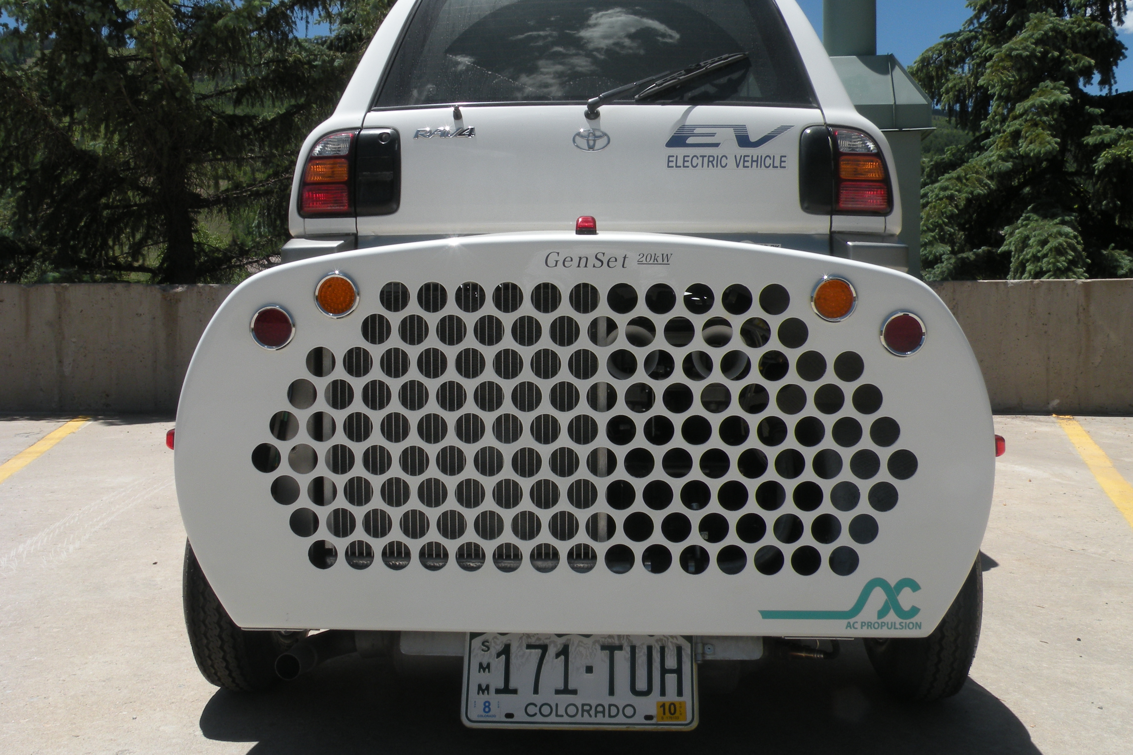
The LongRanger III is equipped with ACPropulsion's
BackTracker steering system.
This system is designed to keep the trailer directly behind
the tow vehicle whether the vehicle is moving forward or backward. The
trailer hitch and ball each hold sensors that determine the trailer’s angle to the
vehicle. The wheels also hold sensors that determine the trailer’s speed
and direction (forward or reverse). Between these
systems a PCB controls the directional inputs to a servo motor which
adjusts the wheel pitch based on those inputs. There is no
software involved in the system.
The following pictures show examples of each of the components of the BackTracker steering system
https://tzev.com/images/T_system_131_back_tracker.jpg
https://tzev.com/images/T_system_132_back_tracker.jpg
Pots to refine and adjust the steering system
https://tzev.com/images/T_system_134_back_tracker.jpg
https://tzev.com/images/T_system_135_back_tracker.jpg
The hitch ball. Note the machining that accommodates the ball sensor in the four (4) pictures to follow
https://tzev.com/images/T_system_137_back_tracker.jpg
Note the two (2) lag bolts and lock nuts under the 2x2" receiver. We added these to eliminate all motion from the hitch coupling system. This ensures that the hitch & ball remain rigid to the vehicles frame at all times. With this modification the trailer is perfectly quiet behind the vehicle and the steering geometry reads the precise angle of the trailer.
https://tzev.com/images/T_system_139_back_tracker.jpg
Note the Blue cover on the hitch assembly. It houses the corresponding coil sensor that reads the hitch angle from the balls angle.
https://tzev.com/images/T_system_141_back_tracker.jpg
Here are the wheel sensors. This is the method of reporting speed and direction back to the PCB
https://tzev.com/images/T_system_143_back_tracker.jpg
https://tzev.com/images/T_system_144_back_tracker.jpg
The following set of pictures show the rack and pinion (worm gear) assembly. This assembly also holds the gearing system
https://tzev.com/images/T_system_146_back_tracker.jpg
https://tzev.com/images/T_system_147_back_tracker.jpg
https://tzev.com/images/T_system_148_back_tracker.jpg
The servo motor has a white support rim where a colar mounts to ensure water tight operations
https://tzev.com/images/T_system_150_back_tracker.jpg
https://tzev.com/images/T_system_151_back_tracker.jpg
https://tzev.com/images/T_system_152_back_tracker.jpg
This is the interior of the servo motor gear housing
The rack and pinion worm gear / ball bearing system are shown here. This takes lateral pressure off the servo motor and allows smooth controlled operations.
https://tzev.com/images/T_system_155_back_tracker.jpg
https://tzev.com/images/T_system_156_back_tracker.jpg
https://tzev.com/images/T_system_157_back_tracker.jpg
https://tzev.com/images/T_system_158_back_tracker.jpg
The next two pictures show the BackTracker steering in operation. Note, as the front wheels of the vehicle turn, the BackTracker steering corrects the trailer to remain directly behind the vehicle.
https://tzev.com/images/T_system_160_back_tracker.jpg